
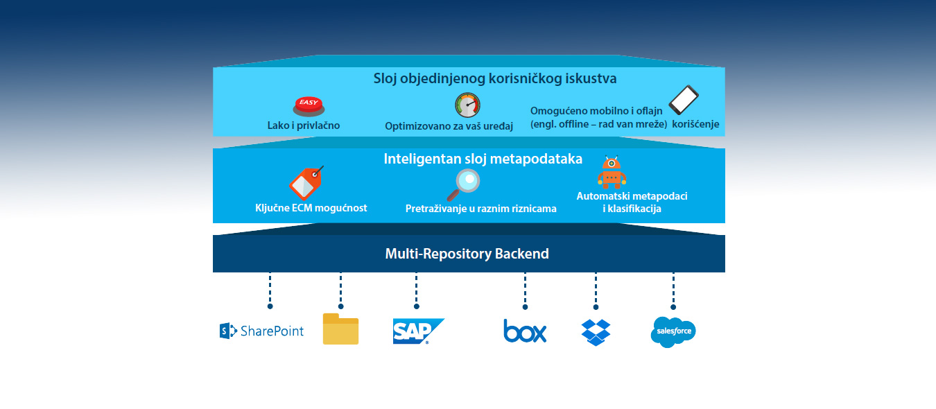


The Tp.v56.pb801 schematic diagram can be divided into several functional blocks, including:
The is a widely used universal "three-in-one" LED TV motherboard that combines the main system board, power supply, and backlight driver into a single PCB. It is commonly found in 32-inch to 42-inch televisions from various brands. Core Circuit Sections
: The primary side of the power supply contains dangerously high voltages (over 300V DC on the main filter capacitor). Always use an isolation transformer when working with an open chassis, and ensure the capacitor is completely discharged before soldering.
Powers the USB ports and serves as the source for lower voltage regulators.
This public link is valid for 7 days and shares a thread, including any personal information you added. This link or copies made by others cannot be deleted. If you share with third parties, their policies apply. Can’t copy the link right now. Try again later.
The Tp.v56.pb801 schematic diagram is a valuable resource for engineers, technicians, and electronics enthusiasts who want to understand and work with this complex electronic component. By following this comprehensive guide, you can gain a deeper understanding of the component's internal structure and connections, and work with confidence.
To help you find the exact documentation or parts for your repair, could you share the TV is showing (e.g., clicking sound, flashing light, blank screen)? Additionally, knowing the brand and model of the LCD panel inside the TV can help determine the correct firmware and jumper settings. Share public link
Understanding the TP.V56.PB801 LED TV Board: A Technical Guide and Schematic Analysis